Cubic Boron Nitride, generally shortened to CBN. The material could only be synthesized in lab before the early stage. In the early 21st century, it was firstly found in nature by an international research team composed of geologists from China, the United States, and Germany. In the same year, scientists and relevant research institutions from China and Germany discovered this substance in the Qinghai Tibet region of China. It formed crystals under high temperatures of 1300 ℃ and 118430 atmospheric pressures. The material hardness is second only to diamond and far higher than other materials. So, CBN and diamond are collectively referred to as super hard material.
In the 1970s, several countries including China, the United States, the United Kingdom, and the former Soviet Union successively developed CBN sintered bodies for cutting - polycrystalline cubic boron nitride (PCBN). Since then, cubic boron nitride has been used for cutting high hardness ferrous materials such as iron and steel with its superior cutting performance.
It could be easily understood through the comparison chart of the hardness and toughness between CBN and other materials.
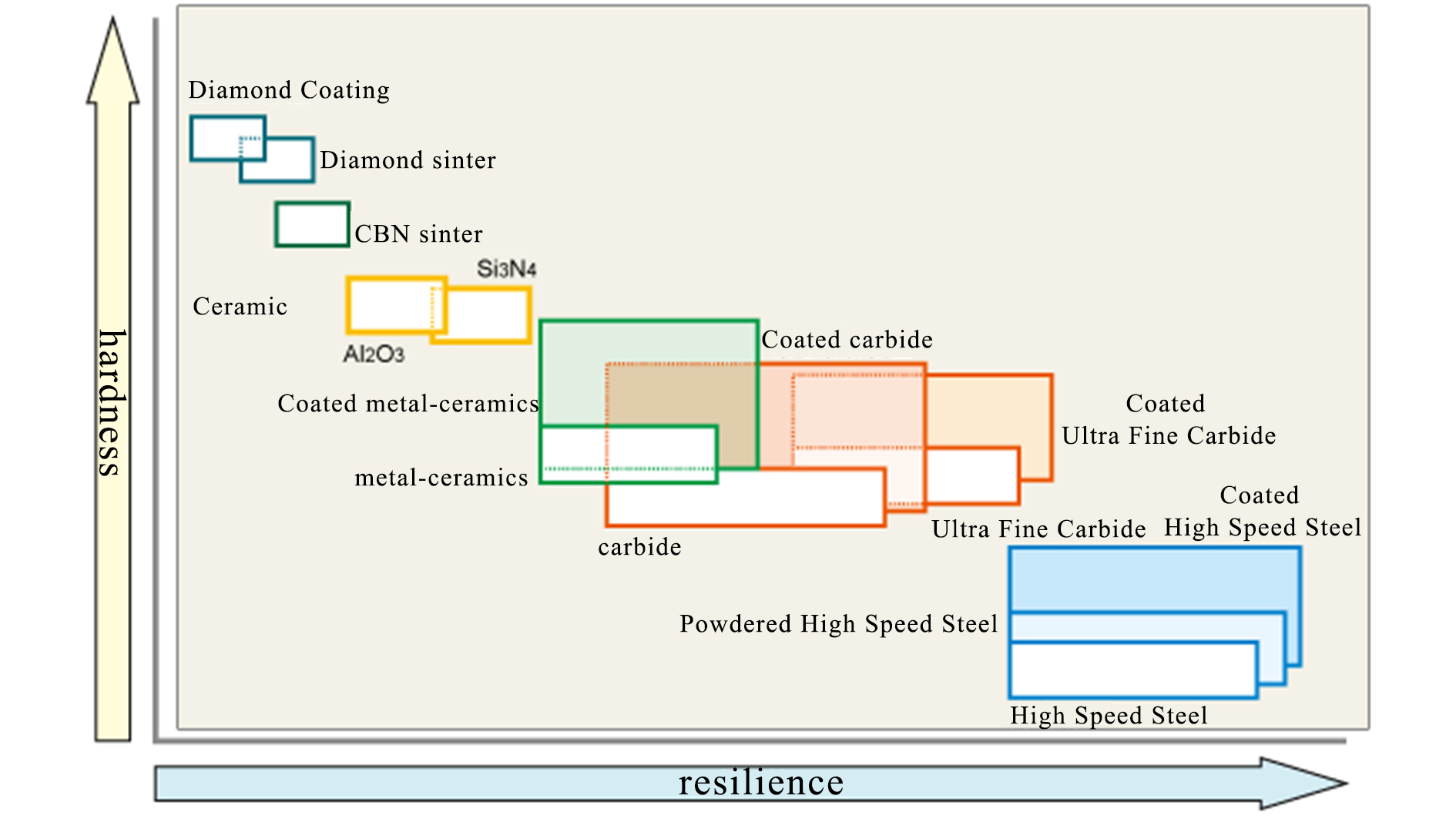
一、Advantages of CBN Inserts:
1、High hardness and abrasive resistance. The microhardness of single crystal CBN ranges from HV8000 to 9000, which is currently known as second only to diamond, while the hardness of PCBN is generally HV3000 to 5000.
2、Good performance on stability and hardness under high temperature. The heat resistance of CBN can reach up to 1500 ℃. And its hardness at 800 ℃ is same as the hardness of Al2O3/TiC ceramics at normal temperature. Therefore, CBN has an advantage over PCD in terms of its high-temperature resistance.
3、Excellent chemical stability. CBN has high antioxidant capacity and does not undergo oxidation at 1000 ℃. It also does not undergo chemical reactions with iron based materials at 1200-1300 ℃.
4、Good thermal conductivity and low friction coefficient.
二、Common Structures of CBN Inserts:
1、Solid CBN Inserts
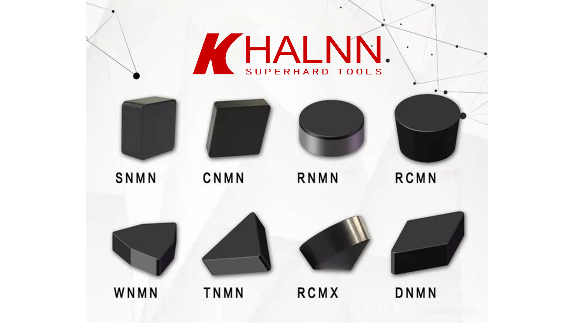
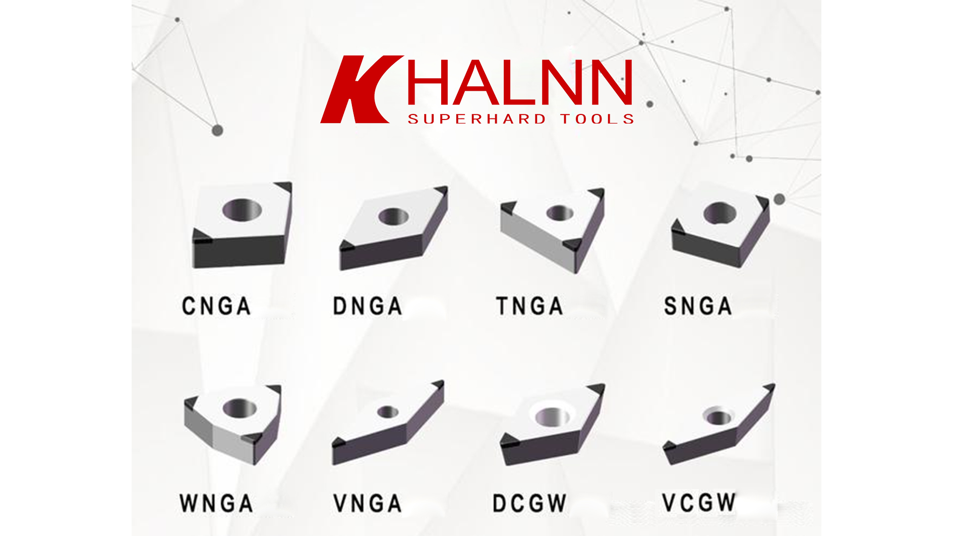
2、PCBN Inserts
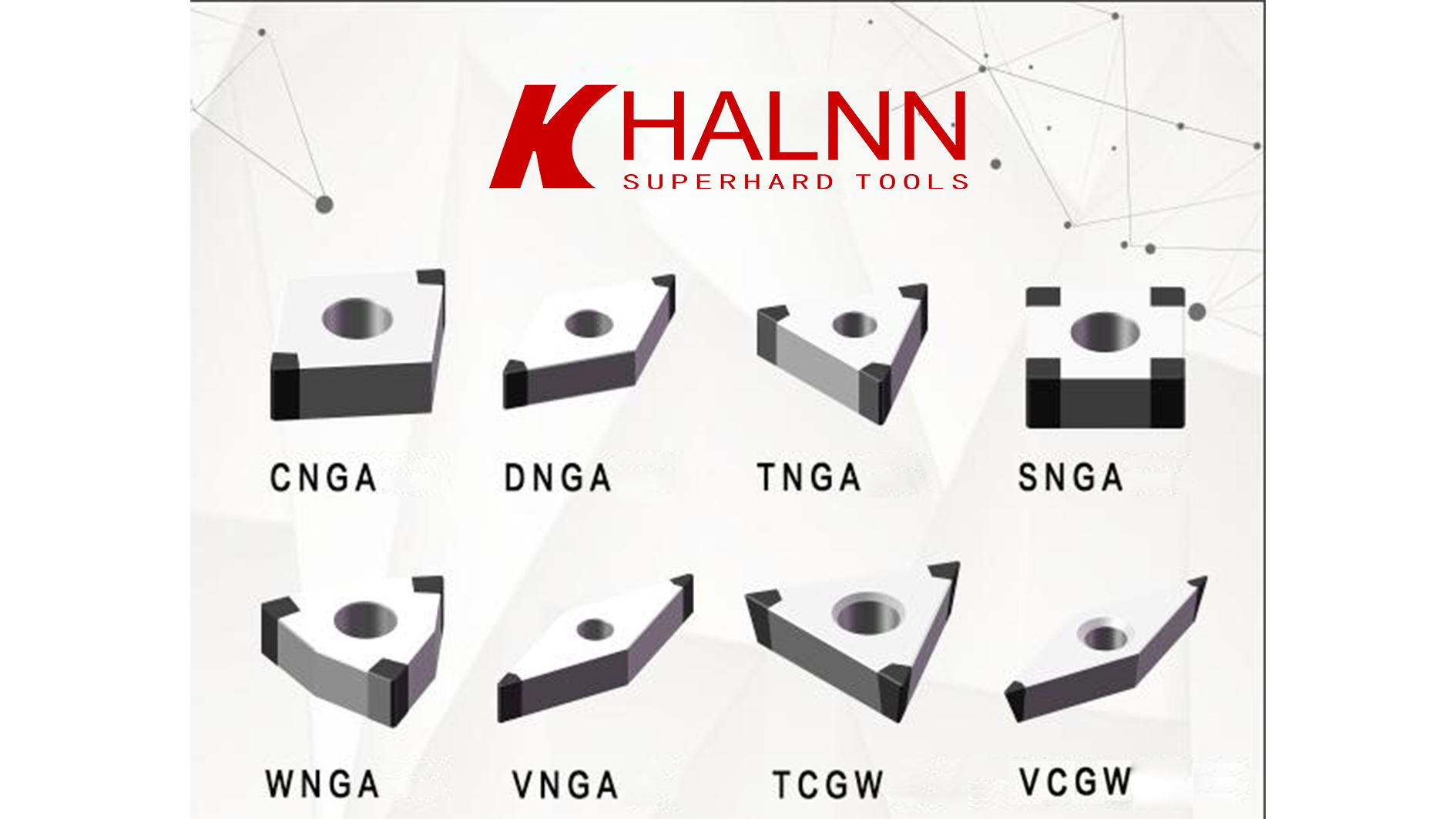
3、Brazed CBN Inserts
三、Application of CBN Inserts from Halnn:
1、Materials of Workpiece:
High Hardness Cast Iron (Above HSD75)
High chromium cast iron, alloy cast iron, nickel hard cast iron, and white cast iron are all high hardness cast iron. The typical workpieces are rollers and industrial pumps. BN-K1 and BN-K10 series of CBN inserts, were developed by Halnn, have a significant advantage in processing high hardness cast iron.
High Hardness Steel (HRC45-68)
High manganese steel, high-speed steel, and hardened steel are included. Typical workpieces include rolling mortar walls, high-speed steel rollers, hardened gears/gear shafts, bearings, ball screws, molds, etc. BN-S10, BN-S20, BN-S200, and BN-H10 series are highly recommended for this material.
Grey Cast Iron (HT150/200/250/300)
The engine block/cylinder head, brake discs, brake drums, pulleys, clutch pressure plates, etc. are all made from gray cast iron. BN-S300 and BNK30 series, developed by Halnn, are recommended for high-speed machining on this materials.
Other Hard to Machining Materials
BN-S300、BN-S200、BDN80 series, developed by Halnn, are recommended for workpiece of this type materials, such as powder metallurgy, high-temperature alloy, and high hardness surfacing/spray welding/laser cladding/thermal spraying materials of nickel based, iron based, and cobalt base.
2、Five Application Sectors:
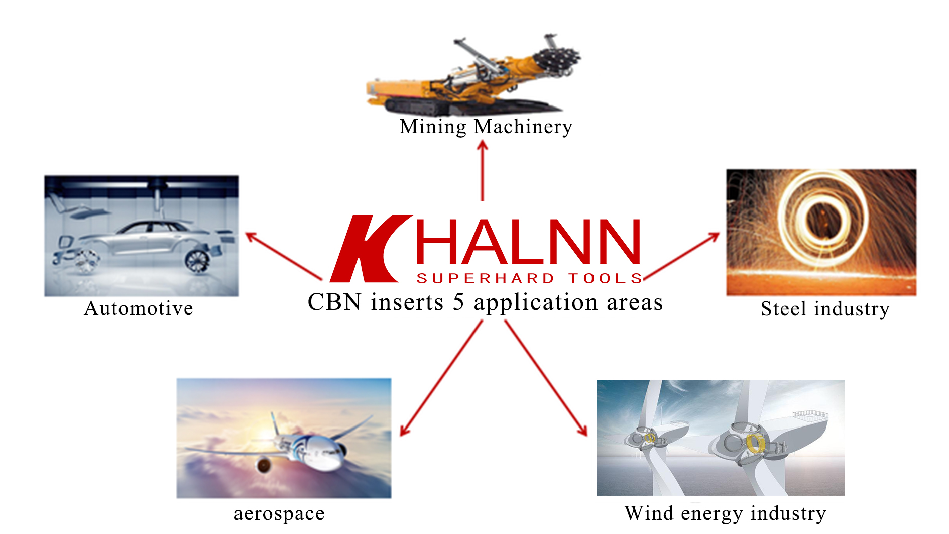
四、Common Processing Techniques
1、CBN Inserts Performance Parameters
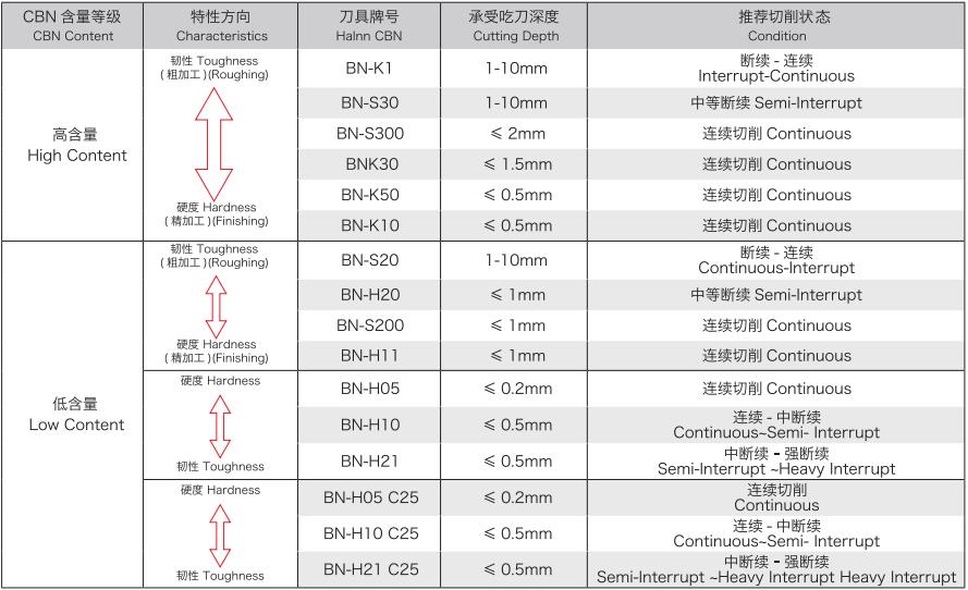
2、Recommended Cutting Parameters for CBN Inserts
For rough machining, it is necessary to ensure a high metal removal rate and necessary tool durability as much as possible. Therefore, it is generally preferred to choose the maximum cutting depth, followed by a larger feed rate. Finally, according to the tool durability requirements, the appropriate cutting speed can be determined. For precision machining, the first step is to ensure the machining accuracy and surface quality. Therefore, a smaller feed rate and cutting depth are generally selected, while a higher cutting speed shall be chosen as much as possible.

3、Suitable CBN Inserts Selection
Generally speaking, it includes the selection of holders or cutters model and the selection of inserts model (including insert edge tip arc).
4、Selection of Holders for CBN Turning Inserts
The PCBN inserts has a central hole for clamping and can be matched with a standard indexable carbide holder.
Due to the lack of a central positioning hole for the solid CBN inserts, C-type upward press turning holder (i.e. CBN turning holders) are often used, with a focus on selecting the size of the blade, the main deviation angle of the turning tool, the shape of the left and right, and the insert. For example, commonly used external surface turning tool holder CCLNR3232P12; CRGNR3232P; CSSNR3232P1; CSRNR3232; CSXNR4040S15 and other models.
Taking CRGNR3232P tool holder as an example, the letters represent the following meanings in order:
C- clamping method is upper pressing type
R-the shape of the solid insert(round)
G- Turning insert main deviation angle (45 degrees)
N-Solid insert side clearance angle (0 degree)
R-Right side
3232-Size of holder (Height * Width)
P-Length of holder (170mm)
5、Selection of CBN Inserts Models
For example, CBN insert model SNMN120712 sequentially includes shape, side clearance angle, tolerance level, clamping type (slid CBN blades are mostly represented by N), edge length, edge thickness, and edge tip radius.
The shape of CBN inserts is decided based on the shape of the workpiece, the side clearance angle is decided based on the material of the workpiece, the tolerance level is decided based on the accuracy requirement, and the cutting-edge length, thickness, and edge tip radius is decided based on the cutting amount of the workpiece being processed.
For rough machining, the maximum feed rate could be decided according to the edge tip radius, or be calculated through an empirical formula; For finish machining, the feed rate could be decided through calculation according to the surface roughness requirements of the workpiece.
The reference table for selecting the feed rate for rough machining is as follows

Formula for feed rate of rough machining:
Fr=0.5 R
R-Edge tip radius (mm)
Fr-Feed rate for rough machining (mm)
A tool configuration table will be provided by Halnn. As long as customers complete the table, Halnn will select suitable inserts accordingly.
五、Common forms of CBN insert wear
1、Wear patterns in continuous cutting
Tools Flank Wear
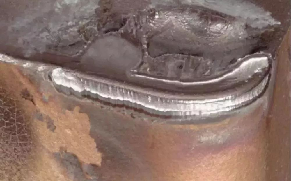
The most common form of wear is formed by friction between hard particles in the tool and workpiece material. Severe wear can lead to poor surface roughness and dimensional accuracy of the workpiece being processed, requiring replacement with new CBN tools.
The main reason is that the cutting speed is too fast, the feed rate is too large, and the side clearance angle of the tool is too small, causing wear on the pressure surface.
Crater Wear
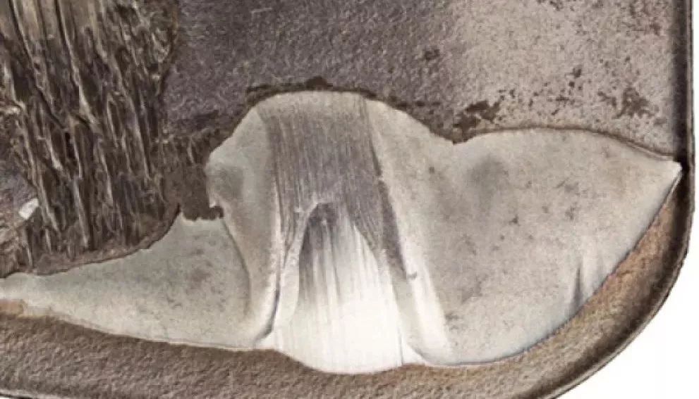
It occurs on the front cutting surface of the insert and is caused by a chemical reaction between the workpiece material and the cutting tool. Crater wear can cause chip handling to deteriorate, affecting the quality of the machined surface, and excessive crater wear can weaken the cutting edge and possibly lead to breakage.
The main reason is that the main deviation angle is too large, the feed rate is too high, and the cutting speed is too low, resulting in boundary wear.
2、The form of damage in intermittent cutting
Broken
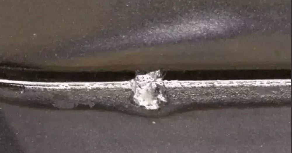
This is a common form of damage when CBN cutting tools intermittently process steel and cast iron. It is a small notch generated on the cutting edge, with several small notches on the edge or a small piece broken off. If the tool with a slightly chipped edge can continue to cut within the allowable wear limit, it needs to be replaced if it exceeds the tolerance.
Cracked
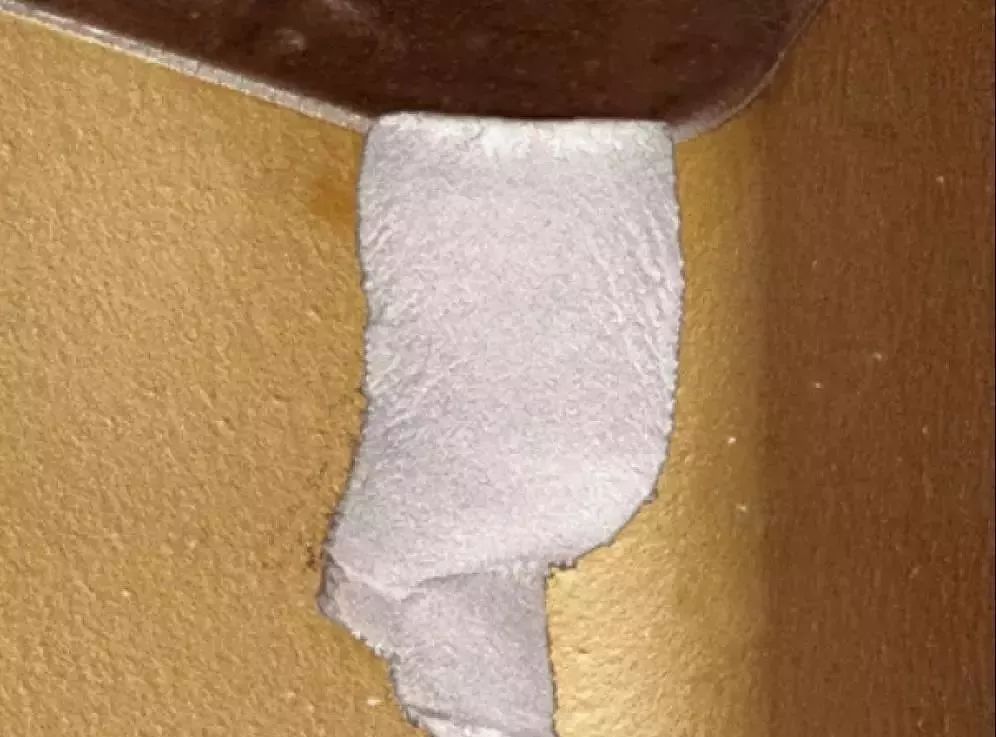
It is a common form of damage that occurs when continuously cutting high hardness materials or interrupt cutting workpieces. This is due to the excessive impact load during intermittent cutting of high hardness workpieces and the early damage that occurs after a short period of cutting. Although the cutting conditions are appropriate, if the tool is not replaced in time after a long period of cutting, large pieces of fracture occur due to the fatigue of the tool material.
In addition to the two types of damage mentioned above, there is another form of peeling: shell like peeling often occurs on the front cutting surface when milling steel and cast iron end faces. To deal with such cases, the cutting speed can be increased, the feed rate can be reduced, and a insert with negative chamfers and passivated edges can be used.
For all inquiries, please fill in the form below (* are required) to send us a brief message, and we will get back to you as soon as possible.